Anatomy of a Project

Pogo, the Balancing Robot

Project Conception

Oct. 5, 2001 Sitting in Prudhoe Bay, Alaska, with some spare time on my hands and thinking about taking a new direction in my robot development. I had recently seen a short piece on TV about a guy that used purely analog techniques to build multi-legged robots. I started sketching up some leg mechanisms. I moved on to the question of balance and then thought about what it would take to build a single point balancing robot. I could see taking this device and dropping it on the floor where it would recover its balance. From there I could envision a one wheeled robot or even a hopping robot. This seemed like a good project - technically achievable but very challenging, unique, low cost, could impress my friends, could start low tech(1-D balancing) with no upper limit, new sensors to play with, etc.

Oct. 9 Completed a sketch of what a balancing robot would look like. Used a servo-driven counterweight arm mounted on a stepper motor to give 2 degrees of counterbalance. The height would be about 12". It would use an AVR uC, lithium batteries, flexible circuit board.


Getting the Components Operational

Oct. 10 The key ingredients to make this work were a tilt sensor and the servo (the stepper as well, but that would be phase II). A little web research on tilt sensors revealed that the current vogue is electrolytic sensors. These are effectively a conductive liquid sealed into a small cell with some sensors. As the internal geometry changes with level the output signal changes. Of course, like all other sensors, they don't put out a convenient 0 to 5 volt signal. These need an AC excitation voltage and output a varying strength AC waveform. They all sell conditioning electronics which cost2 or 3 times as much as the sensors. I figured I could do the excitation stuff myself so I ordered 2 +- 40 degree tilt sensors from Nanotron for $24.00 each. I wasn't able to talk him out of these as free samples but he will directly sell small quantities which suited me just fine.

I also did some research on servos - looking for small, tough (ball bearings) and relatively strong (a Futabo S3001 looked about right). These type of servos are, of course, expensive ($65.00). Of course you could go for digital servos running $160. I ended up settling for a cheap Airtronics unit that I borrowed from my sons race car.

Oct. 15 The tilt sensor arrived about a week later (slower after 9/11). It required an AC excitation (mentioned sine wave) at 17KHz. I programmed an AVR ATMEGA163 to produce a 17KHz square wave and monitored the output. The output was a slightly slanted square wave centered at 2.5 volts that increased/decreased in amplitude as the sensor was tilted. I thought about picking off the peak voltage somehow and measuring that with the A/D or measuring RMS. I ended up triggering the A/D conversion every cycle and have it do a conversion through the tilted section. As long as the process is repeatable it should produce solid results. In order to make this work I did have to slow the frequency down to about half of the 17 KHz, but it did seem to work very well. The literature indicated that it could not be DC and that Nanotron uses a higher 17KHz signal, but nothing more.

It took me an afternoon and long evening to get to the point of declaring success with the tilt sensor.

Oct. 18 Attention then turned to the servo. I had not worked with servos too much but knew that they were fairly simple to control. I finally found information showing that one needs a periodic pulse with a width ranging between 1 and 2 ms. The frequency of the pulse is relatively unimportant but about 40 Hz seems common. In order to save on my AVR timers, I used the same TCNT2 as the tilt excitation for timing, with an extra divider, for my pulse rate generator. I used TCNT0 (8 bit) for the pulse rate delay calculation. Pretty straightforward.

Oct. 20 Now to find a servo. I wanted a Futaba S3001, but they were too pricey for experimenting. I found an Airtronics servo in my sons dune buggy racer and then bought a Futaba S3003 (the basic servo) for $12. After a little experimenting I found the Airtronics worked better so I stuck with it. I was able to move the servo by changing the pulse width - all was good. I wrote a simple program that would change the servo output as a function of tilt. This worked fine and the servo would move as I tilted the sensor.

Building a 1-D Test Model Oct. 24 I built a crude 1-D test unit using a piece of aluminum molding with a chopstick for a weight arm and battery for a weight and mounted it, with limit stops, to the side of my wood table.

Oct. 27 Now to work out the control mechanism. As a first attempt I could see a PID controller with Tilt = 0 as setpoint to control the servo. Here is the C code for my original PID routine:

// PID Control Routine - 3 modes

// Attempts to match pv to setpoint by adjusting output.

// All inputs in percent (0 to 100), gain of 100 = gain of 1

// Kp, Ki and Kd are Proportional, Integral and Derivative gains x 100
 

INT16S PID(INT16S pv, INT16S setpoint, INT16S Kp, INT16S Ki, INT16S Kd)
{
INT16S err;
static INT16S pi = 50;
static INT16S err0;
INT16S pd, pp;
INT16S output;

err = setpoint - pv;

pi = pi + ((err * Ki) / 100);
if (pi > 100) pi = 100;
if (pi < 0) pi = 0;

pd = ((err - err0) * Kd) / 100;
err0 = err;

pp = (err * Kp) / 100;

output = pi + pp + pd;
if (output > 100) output = 100;
if (output < 0) output = 0;

return output;
}

I had no success making this stable. I decided I needed a good, interactive PC interface instead of the text terminal monitor I had been using so far so that I could tweak settings on the fly without reprogramming.


A Better PC Interface Oct. 31 I had done quite a bit of work in the past on PC interfaces. I decided I had four reasonable choices: I decided the last option would get me to the end the soonest. I modified, and simplified, the Mailbox slave routines and added them to the Pogo program. I had this operational over the course of two evenings.

Nov. 4 The Mailbox PC interface allowed me to read variables and poke variables to/from the Mailbox array. It would parse the data from raw bytes to and from integers. I decided I needed a scrolling data screen (similar to a terminal program) which I created with improvements over a terminal program - scrolled from top down, editable line for headings. I also made miscellaneous improvements to the main Mailbox interface form.

Nov. 6 Now well sidetracked by the Mailbox upgrades, I decided that I really wanted a custom interface. I had planned to convert the Mailbox server to an ActiveX component - this seemed like the time. I haven never really intuitively understood object programming in the Visual Basic world. Collections never seem to do what I want and everything seems non-intuitive. Never-the-less, I blundered through and created an ActiveX interface. Again I learn - if you ever plan to make your project a component then start-out with that plan. Revising a conventional program to an object model is tough.

I can now get and send variables with simple calls to the Mailbox object. I wrote the Pogo window in the same program but using object calls, partially to test the new object. This is easier than running a separate Active.X server while Mailbox is still in Beta testing.

Nov. 12 I now have a first pass Pogo interface screen developed - the black line is tilt, red is servo position, green is setpoint. The calibration variables are used to define min, max and center for the tilt sensor and for the servo. I can now play with the settings and see what she does!

Getting the 2-D Model Operational 
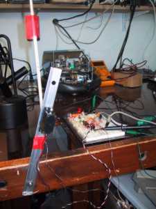
Nov. 15 Pogo is pretty twitchy. If I set the gain high enough to allow it to correct itself from a 20 degree tilt then it jumps all over the place. Time for a general overhaul that included solidifying the servo mounting to the rod, fixing a tilt signal that is jumping around by about 5% and improving the weight connection. I found that the A/D conversion was sometimes not completing within a tilt excitation cycle so I reduced the excitation frequency to about 4 KHz. I also had to redo my A/D power wiring per the AVR manual - separate A/D ground, caps on power feeds. This stabilized the signal - it now had noise of +- 3 counts out of a 200 count range, down from +- 10 counts.

Nov.20 I decided straight PID control would not cut it. The setpoint was not obvious - should it be straight up or should it be the current balance point. I decided to start with a straight ratio of servo angle to tilt angle. A little mathematics (2 evenings of work) told me that the servo angle required to be at the balance point would be close to a constant ratio, and opposite to, the tilt angle. So I programmed the servo to simply always move to the balance point. This didn't really work either because of the time lags in the control. The weight was always moving to a location that was already history. I needed to have the weight anticipate the location. I therefore added a derivative component. Another problem with the straight ratio model is that there is no advantage to standing straight up. The model is happy anywhere that it is balanced. I therefore added a weak reset component to try to slowly ease the tilt angle back to level.

The net result of these improvements was a robot that would occasionally balance but not very often. It was still too twitchy. I knew I would have to look at the momentum issues. When the servo turns it imparts an opposite momentum force on the robot then a same direction momentum once the weight gets moving and when it stops. I needed to do some math to predict what action to take given the existing tilt, tilt velocity and acceleration conditions and then execute the result as a series of longer duration planned moves. I could see the complexity mounting.


Nov.25 I spent most of a 3 day working weekend on Pogo or Mailbox. I did some research about similar systems. I discovered a minor subculture devoted to "inverted pendulum" problems. It appears this is a classical mechanical system that has been notoriously difficult to solve mathematically. The versions most studied are free pendulums on a moving cart (move the cart - balance the pendulum). The other is the Futura pendulum, a free hanging powered pendulum that can rotate 360 degrees and is also rotated around a vertical axis. Lots of really complex math. Scientists have spent much of their careers devoted to these problems.

I had already come to the conclusion that I would need several different modes - swing-up, balanced, losing balance. The action would be a series of "throws" and "catches". At any given tilt, tilt velocity and acceleration and servo angle there is a servo action that can correct the balance (the throw). Near the end of the throw cycle corrections would be introduced based on what actually happened (the catch).

I decided to work on the Swing-up mode. To do so I would need control of all parameters from the PC so I could play with settings without reprogramming. Mailbox was not behaving well - I had figured out why. It performs buffering of all read and write requests. When I changed to the object model I had forgotten to buffer part of the data. This repair took most of a day as I got bogged down in collections and other object issues. Communications programs are tough slugging at the best of times. This buffering business was the most complex part. I also did some additional clean-up and tried to separate the Pogo file cleanly from the Mailbox program so that Mailbox could be split off as an Active-X component. This too did not go as smoothly as I had hoped. But I finally got everything working pretty well. I was still getting a little data crossover when two high rate reads were going on. Next weeks cleanup.

I designed a simple swing-up routine that would take Pogo from its stationary point to near balanced. The routine started from a known servo location, moved to a second definable location, stayed there for a definable time and then ramped back to 0 angle over a period of time (definable). All the definable values were controllable from the PC. After a couple hours I was able to get Pogo to swing up and come almost to a balance. This was fairly repeatable. I was at least convinced that I could likely incorporate a Balanced mode and have it swing up and balance. Of course I was swinging up from a known position. Another matter to swing-up from any set of parameters.

Dec. 1 Sidetracked by my ATMEGA128 board. Shall return.